The Ion Pumpy Thing: a hand drawing, rebuilt and explained
In December 2024 a hand-coloured sketch of a machine appeared on X with the caption “Ion Pumpy Thingy. Make massive Arcs.” This page rebuilds that sketch in 3D, walks through it part by part, sets out the measured facts behind each part, and what it would take to build it and make it work.
It belongs to the engineering this site exists to bring into the open: taking electricity straight from a plasma with no boiler and no turbine, the direct-conversion architecture that Ashton Forbes' investigation keeps returning to. For another plasma route this site follows, see the chapter on lattice confinement fusion.
The drawing and where it came from
The bottom line. It is one sheet of paper showing a sealed, water-cooled tube. Inside are a glowing gas, a stack of metal screens and a piston. The sheet says the piston squeezes the gas slowly, 10 to 30 times a second, and the screens take electricity out.
The X account @TMBSPACESHIPS posted the sheet on 1 December 2024 [The drawing]. Its title, in the author's capitals, is “CLOSED Cycle PLASMA AMPLIFIER / DYNAMIC PLASMA ALTERNATOR”, and it carries the dedication “ION Pumpy thing for Ashton!”. It is the source document for everything on this page.
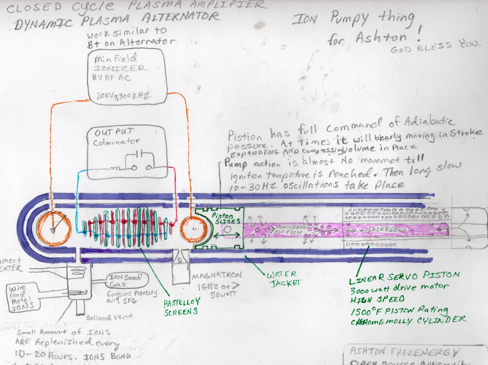
Read from left to right, the sheet shows a rounded closed end, an orange round body, about eighteen thin rings drawn alternately red and teal, a second orange body, a green piston, and a rod running to a motor. A small pot hangs below the left end. Two boxes above the tube stand for electronics.
Go deeper: the labels as written, and the scale we assumed
- Upper box: “Min Field IONIZER HV HF AC 20KV@300KHZ”, with the note “work similar to B+ on Alternator”. Orange wires run from it to the two orange bodies.
- Lower box: “OUT PUT Colmunator”, holding a coil, a capacitor and two terminals. A blue wire joins the teal rings and a red wire joins the red rings.
- The rings: “HASTELLOY SCREENS”. Hastelloy C-276 is a nickel alloy with 16% chromium and 16% molybdenum that melts at 1,323 to 1,371 °C and is not magnetic [Haynes datasheet].
- Below the tube: “MAGNATRON 1GHz or > 50 WATT”, “WATER JACKET”, “ION Seed Gas Contains Mercury and SF6”, “Wire Feed metal IONS”, a filament heater and a “Selinoid Vent”.
- The drive: “LINEAR SERVO PISTON 3000 watt drive motor”, “1500°F PISTON Rating” (816 °C), “CHROMEMOLLY CYLINDER”.
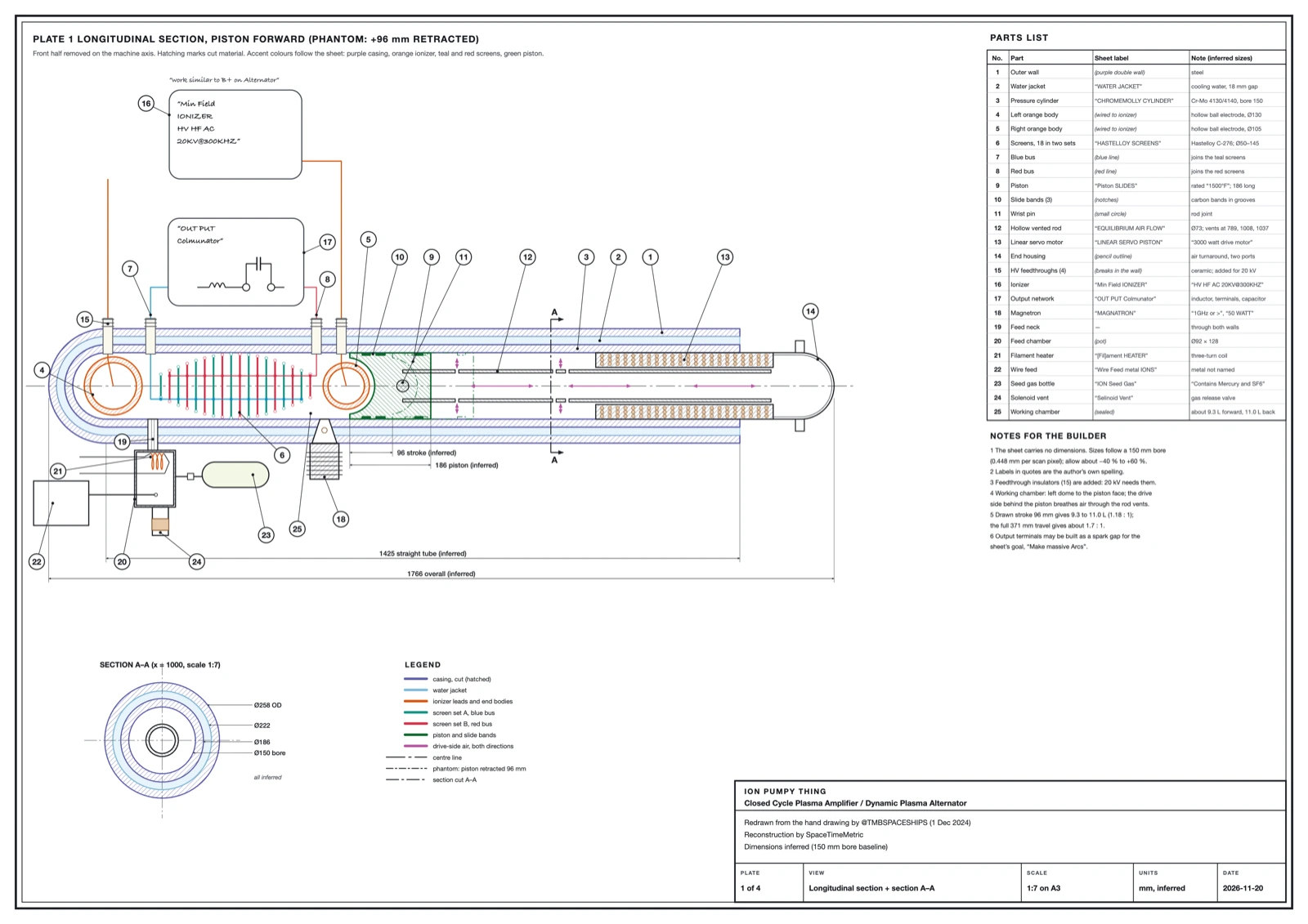
The sheet has no dimensions. Our model assumes a 150 mm bore, which makes the machine about 1.8 m long and 260 mm across. Every size could be about 40% smaller to 60% larger. With that scale the sealed chamber holds 9.3 litres with the piston forward and 11.0 litres at the end of the stroke the sheet draws.
Technical drawings
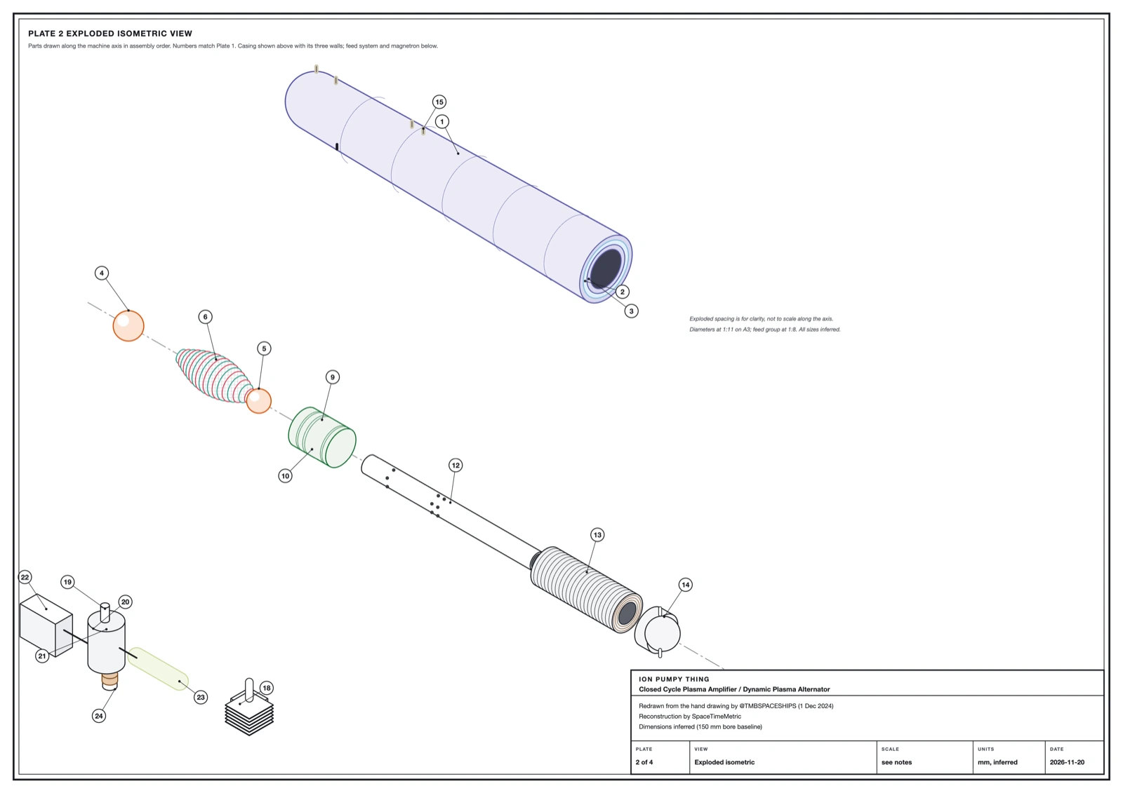
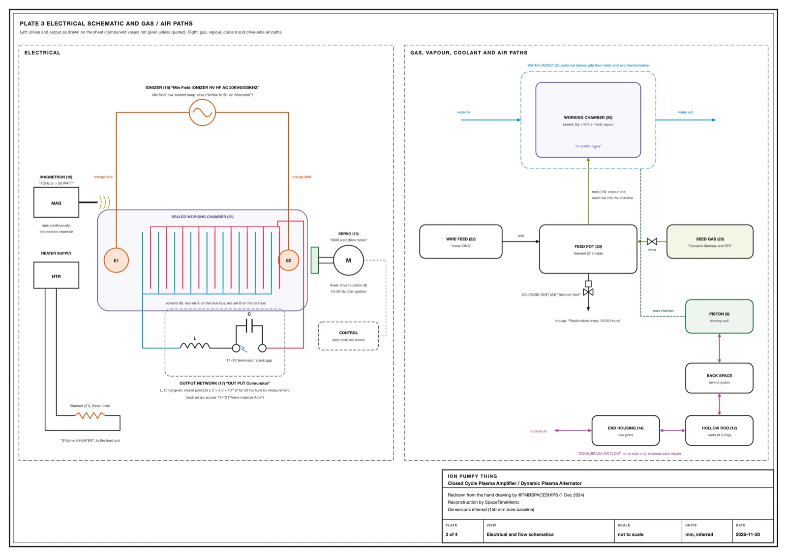
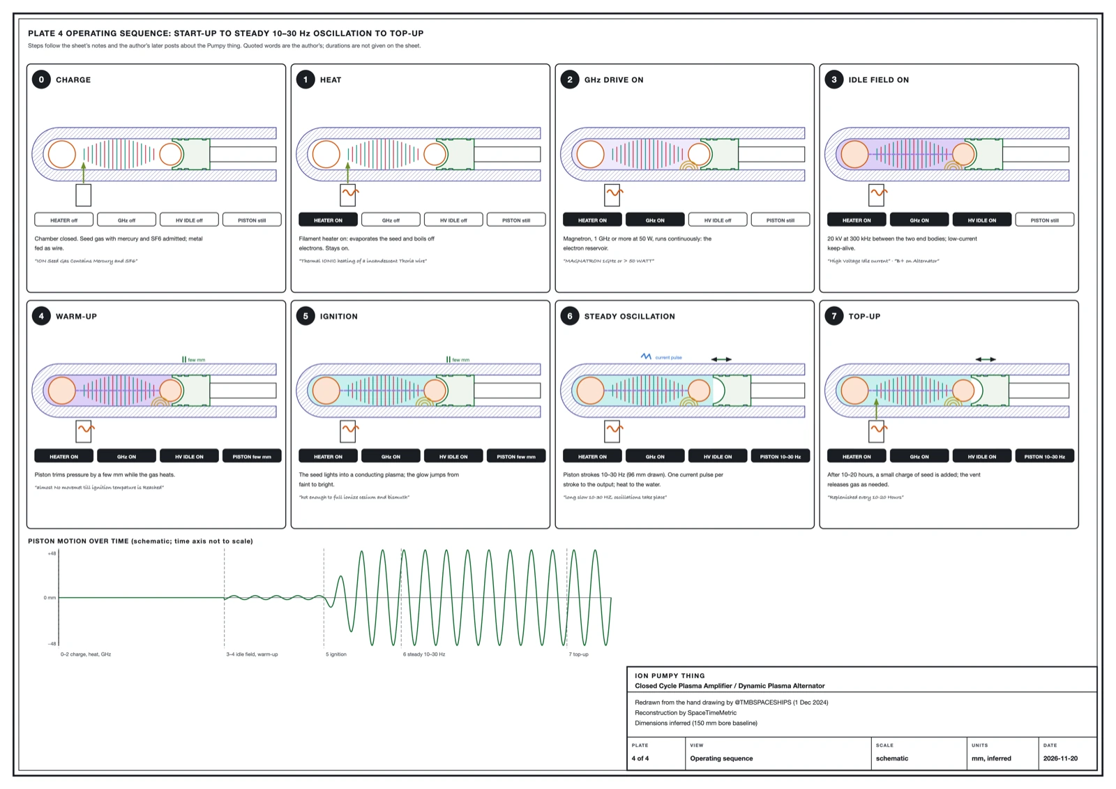
The bottom line. These four drawings turn the sketch into something a workshop can read: a section with every part numbered, an exploded view, the wiring and gas route, and the running order. They are our reconstruction, drawn to the 150 mm bore we assumed.
The 3D film
The bottom line. We built the machine in 3D from the sheet's own labels and filmed it running as the sheet describes. The film is 3 minutes 59 seconds long, covers the machine and the two related designs the author drew, and its captions say which parts are drawn, which are the author's words and which are our estimates.
- 0:00The drawingThe scan dissolves into the 3D model at the same side-on view.
- 0:10One design, drawn many timesThe five parts the author draws again and again (seed gas, hot electron emitter, high-voltage drive, gigahertz electron drive, slow mechanical modulator) fly to their places on the machine.
- 0:25Opening it upThe cutaway: chromoly cylinder, water jacket and a scale bar.
- 0:33The sealed chamberThe two orange end bodies, the eighteen screens and the piston.
- 0:42Seed gas and the hot emitterThe feed pot, with its filament as a small thoriated emitter.
- 0:53The gigahertz electron driveThe magnetron as a steady electron reservoir, sending microwaves into the chamber.
- 1:03The idle fieldThe ionizer as a low-current keep-alive supply: a thin, steady glow along the axis.
- 1:15Waiting, barely movingThe piston trembles by a few millimetres before ignition.
- 1:24IgnitionThe glow jumps from faint to bright as the seed metals ionize.
- 1:37The slow oscillationStrokes of 10 to 30 a second, shown slowed, with a volume gauge; ions move with the piston.
- 1:50Collecting the currentOne current pulse per stroke on both buses; the screen sets flash and the output network arcs.
- 2:04Behind the pistonThe motor, the vented rod and the air that breathes on the drive side only.
- 2:14Sibling 1: the Low Frequency Plasma ModulatorBuilt from the author's 1 July 2025 drawing: diaphragm, heated thorium-coated antenna, 60 GHz feed, magnet and plume.
- 2:30Sibling 2: the Brown-Cahill layoutBuilt from the author's 17 November 2024 drawing: hull, end modules, seed-gas and helium loops, and the plasma envelope.
- 2:46The typed ignition sequenceThe author's 13 February 2026 ignition sequence, played step by step on the Brown-Cahill model.
- 3:06Where the energy goesEnergy in and out, and each energy route the author names, paired with the test that would measure it.
- 3:21The author's theory pageBudker's four-step cycle, in time with the piston.
- 3:33What a test would showMeters on every input, on the output and on the cooling water.
- 3:44Three readingsThe author's material, Ashton Forbes' reading as design options to test, and Making it work: the open engineering.
How it works, part by part
The bottom line. Fill a sealed tube with a gas that turns into plasma easily. Keep it lit with a small high-voltage supply and microwaves. Squeeze and release it with a piston. Collect current on screens that sit in the plasma. The steps below follow that order and say which words come from the sheet.
Charge the chamber
The sheet says: A pot under the tube feeds “ION Seed Gas” that “Contains Mercury and SF6”, and a “Wire Feed” adds “metal IONS”.
The sheet does not name the wire metal. A later post by the author names cesium and bismuth for this device.
Heat the feed
The sheet says: A “Filament HEATER” sits in the pot.
A hot filament turns mercury and metal into vapour and gives off electrons, as the heater in a vacuum tube does.
Switch on the microwaves
The sheet says: A “MAGNATRON 1GHz or > 50 WATT” feeds the chamber through the wall.
On the author's larger drawings the matching part keeps electrons energised the whole time, so the film's “starter” may run continuously.
Apply the idle field
The sheet says: The “Min Field IONIZER” supplies “HV HF AC 20KV@300KHZ” to the two orange bodies and is said to “work similar to B+ on Alternator”.
The author later calls this a “High Voltage Idle current”: a small supply that keeps the gas conducting, like the field current that lets an alternator start generating.
Wait for ignition
The sheet says: “Pump action is almost No movemet till ignition tempature is Reached.”
In the author's other posts, ignition means lighting a seeded gas into a steady plasma. For this device the stated threshold is that the gas must be hot enough to ionize the seed metals.
Oscillate slowly
The sheet says: “Then long slow 10-30 HZ oscillations take place.” The piston “has full command of Adiabatic pressure”.
Adiabatic means the squeeze happens faster than heat can leak away, so pressure and temperature rise and fall together.
Collect the current
The sheet says: The “HASTELLOY SCREENS” are wired as two interleaved sets to a box marked “OUT PUT”.
The author later writes that the “screen assembly is collector” of the currents and the seed gas “works similar to electrolyte”.
Deliver it
The sheet says: The output box holds a coil, a capacitor and two terminals. The post's caption: “Make massive Arcs.”
Carry the heat away
The sheet says: A “WATER JACKET” surrounds the “CHROMEMOLLY CYLINDER”.
Top up
The sheet says: “Small Amount of IONS ARE Replenished every 10-20 Hours.”
Go deeper: the squeeze, in numbers
Treat the plasma as a gas of single atoms, so the ratio of specific heats is γ = 5/3. If the piston moves faster than heat can leak to the walls, pressure and temperature follow the adiabatic law.
What this says
The stroke the sheet draws changes the volume from 11.0 to 9.3 litres, a ratio of 1.18. Equation 1 then gives a pressure rise of 32% and a temperature rise of 12% on each inward stroke. If the piston used all the room behind it, the ratio would be about 1.7 and the temperature rise 42%. The sheet's own words fit the smaller figure: the piston is “bearly moving in Stroke”.
Mercury suits a machine like this because it is easy to ionize and its pressure is set by temperature alone. Its first ionization energy is 10.44 eV [NIST ASD]. Its vapour pressure is 0.17 Pa at 20 °C, 37 Pa at 100 °C and 2.3 kPa at 200 °C, and it boils at 357 °C [NIST IR 6643]. SF6 does the opposite job: it captures free electrons and forms heavy negative ions, and in a discharge it breaks down into corrosive sulphur-fluorine compounds [NIST TN 1425]. That chemistry is a sound reason to choose a nickel alloy for the screens.
Microwaves reach into a plasma only while it is thin. Above the cutoff density the plasma reflects them.
What this says
At the sheet's “1GHz or >” the standard model puts the cutoff at 1.2 × 10¹⁰ electrons per cm³; at the 2.45 GHz of a kitchen magnetron it is 7.4 × 10¹⁰. A bright arc is far denser than that. So 50 W of microwaves holds a thin glow and helps the gas light, and the piston and the high-voltage supply do the rest. Constants are from CODATA [CODATA].
The device family
The bottom line. The author drew the same five ingredients several times between 2024 and 2026: a seed gas, a glowing-hot electron emitter, a high-voltage supply, a microwave source, and a slow mechanical pump. The Ion Pumpy Thing is the one version that is sealed and has screens to take current out. On the bench the recipe is a generator; around a hull the author draws it as the field that carries the craft. Energy and propulsion are one subject here.
| Drawing | Posted | What it shows | Slow pump | What the author says it makes |
|---|---|---|---|---|
| Buoyancy system teaching model | 3 August 2024 | Block diagram of a capsule-shaped craft | Not drawn; the post gives a drive below 70 Hz | A plasma shell around the hull |
| Brown-Cahill method | 17 November 2024 | Cross-section of the craft with gas loops | Steel diaphragm, 0.1 to 70 Hz | A plasma shell around the hull |
| Ion Pumpy Thing | 1 December 2024 | Sealed, water-cooled tube on a bench | Servo piston, 10 to 30 Hz | Electricity at two terminals |
| Low frequency plasma modulator | 1 July 2025 | Close-up of one end module, open to air | Steel diaphragm, below 70 Hz | A shaped plume of ions and electrons |
| Low and high frequency sub-system | 2 September 2025 | Block diagram with one end module in detail | Chromoly diaphragm with a drive coil | A plasma shell around the hull |
Three days before the drawing, the author described the idea in words: a seeded plasma “physically pumped back and forth” through an insulated pipe, with wires through the wall, gives “a current potential generation”. On 25 December 2024 the author re-posted the sheet with a one-paragraph recipe: a plasma chamber, coated plates to carry the current out, inductors, and “electric high temperature Servo Pistons to Oscillate the Plasma”.
Go deeper: the numbers that repeat across the drawings
- Below 70 Hz. Every version keeps the mechanical pump slow: 0.1 to 70 Hz on the diaphragm drawings, 10 to 30 Hz on this sheet. The author's stated reason is to keep the heavy ions moving slower than sound.
- 300 kHz. A post of August 2024 gives the high-voltage supply an internal resonance “in the order of 300KHz”. The sheet's ionizer runs at “20KV@300KHZ”.
- 60 GHz and about 1.4 GHz. The larger drawings pair a 60 GHz carrier with a modulation of 1.3 to 1.8 GHz. Two measured facts sit beside those numbers: oxygen in air absorbs strongly in a band centred on 60 GHz [ITU-R P.676], and neutral hydrogen has a line at 1,420.406 MHz [ITU-R RA.314]. The author links 1.41 GHz to hydrogen on one drawing and does not explain the choice of 60 GHz.
- The same emitter. A filament here; on the larger drawings an incandescent, thorium-coated “heated antenna”, said to work “the same fashion as Vacuum Tube Filament Heaters”.
Two readings, two builds
The bottom line. The drawing was made for Ashton Forbes, and he has walked through it on his streams. He and the sheet agree on the heart of the machine: screens that take electricity straight out of a plasma, and a piston that controls its pressure at 10 to 30 strokes a second. Where they read a part differently, each reading is a design option, and both can be built and tested side by side.
| Part | Option from Ashton Forbes' reading | Option from the sheet's labels | How to test both |
|---|---|---|---|
| Screens and output | Direct energy conversion: the screens collect charged particles and make electricity. | The same. The screens are wired to “OUT PUT”, and the author calls them the collector. | Voltage and power across the two screen sets, logged against piston position. |
| Piston | Small movements at 10 to 30 Hz set pressure and density. A magnetic piston could do the job with no moving part. | A mechanical piston: “LINEAR SERVO PISTON”, “3000 watt drive motor”, “CHROMEMOLLY CYLINDER”. | Build the mechanical piston first. Then wind a coil on the same chamber and compare the pressure swing each one gives. |
| Working gas | Air drawn in at the right-hand end, as on the author's open-air drawings. | “CLOSED Cycle”: a sealed charge of mercury, SF6 and metal vapour. The air arrows sit on the motor side of the piston. | Run sealed, then add a metered air inlet. Compare ignition and output. |
| The rings | A row of alternating magnets that steers and synchronises the particles. | “HASTELLOY SCREENS”: two interleaved sets of electrodes in a non-magnetic alloy. | Screens first. Then add ring magnets between them and log any change in output. |
| Energy source | Fusion in the plasma, with boron as a candidate fuel. | A seeded plasma run through a conversion cycle. The author names several candidate sources, set out in the next section. | The heat balance below, with neutron and gamma counters beside the chamber. |
| The ionizer | A cloud of electrons that screens nuclei from each other. | A high-voltage, high-frequency idle supply, likened to the field supply of an alternator. | A Langmuir probe for electron density and temperature with the supply on and off. |
His full walk-through is the stream of 28 May 2026 [Ashton Forbes]. The corner of the sheet is lettered ASHTON FREEENERGY / OPEN SOURCE, and this page is offered in the same open spirit.
The measured facts behind each part
The bottom line. Every part on the sheet is a real kind of hardware with measured physics behind it. The machine as drawn can be built today: a piston-pumped mercury discharge with collector screens in it.
- The ionizer. A 20 kV, 300 kHz supply lights a low-pressure gas between two electrodes. Microwaves help it start and keep the electrons energised.
- The seed gas. Mercury and cesium vapours are standard plasma media. Both were the first fuels of the ion engines launched in the early 1960s [Goebel and Katz].
- The filament. A hot filament gives off electrons, the principle of every vacuum tube and of the thermionic converter [NASA SP-226].
- The screens. Metal electrodes in a seeded plasma pass current to an outside circuit. NASA measured about 10 W from each square centimetre of hot emitter [NASA SP-226].
- The piston. A piston raises and lowers the pressure and temperature of a sealed gas (equation 1).
- The cycle. Squeezing and releasing a hot plasma moves energy into a circuit (equation 3).
- The materials. A nickel alloy for hot fluorine-bearing gas, chromoly steel inside a water jacket, and a servo motor of a few kilowatts are all catalogue items.
Go deeper: how much current screens collect
A plasma shields any electrode inside it within a short distance, the Debye length. Beyond that distance the plasma does not feel the electrode's voltage.
What this says
For an electron temperature of 2 eV and a density of 10¹⁸ per m³, λ_D is 10 micrometres. For the far thinner 10¹³ per m³ that the author quotes for the craft drawings, it is 2.4 mm at 1 eV. Adding a seed gas raises the density and shortens the length, which matches the author's remark that the seed gas increases screening.
The current a cool electrode draws is set by how fast ions arrive at the edge of that layer. This is the Bohm current [Goebel and Katz].
What this says
For mercury ions (M = 200.6 atomic mass units) at 10¹⁸ per m³ and 1 eV the ion sound speed is 694 m/s and J_B is 67 A/m². Goebel and Katz work the same example for xenon at 3 eV and find 118 A/m². With roughly 0.3 to 0.5 m² of screen at our assumed scale, cool screens give tens of amperes at about a volt. A hot emitter set changes the scale: at NASA's 10 W/cm², 300 cm² of emitter delivers 3 kW. The density here is our assumption; the sheet gives no pressure.
Making it work: the open engineering
The bottom line. The sheet is a concept sketch, and four things are left for the builder to fix: where the heat comes from, how hard the piston squeezes, how hot the screens run, and whether a magnet belongs in the chamber. For each one the author has named options, the formulas above give the standard model's predictions to test against, and a specific build and measurement would show the result.
1. The energy source
The sheet's title calls the machine a plasma amplifier, and its corner box is lettered ASHTON FREEENERGY / OPEN SOURCE. The inputs it draws are the ionizer, the magnetron, the 3,000 W motor and the heater. Both converter designs the author cites take their electricity from heat in the plasma, so the builder's first task is to identify the heat and meter it. The author's posts name these candidates.
- A hydrocarbon lit in the chamber. In the post that re-published the sheet, the author describes a chamber where you “ignite plasma with a Hydrocarbon” and heat it. To be shown by: metered fuel flow times its heating value, set against electricity out plus heat to the water.
- Mercury near its vapour transition. The author describes mercury warmed until it “slightly gasses and begins to ionize”, with the current collected by plates in the medium. To be shown by: sweeping the mercury reservoir from 20 to 357 °C (0.17 Pa to one atmosphere [NIST IR 6643]) and logging screen output at each step.
- Cesium and bismuth ionized at hot screens. The author writes that the screens must be hot enough to ionize both. Cesium needs 3.89 eV and bismuth 7.29 eV [NIST ASD]. To be shown by: sweeping screen temperature and watching the cesium and bismuth ion lines appear in a spectrometer as the output rises.
- The electron lattice and the cosmic thermal background. The author proposes that the thermal background of space can be “funneled” by forced plasma collisions into a current of electrons, and that electricity can be shocked out of an electron lattice with no fuel. This is the author's central proposal, and a direct measurement settles it. To be shown by: a sealed run in which electricity out plus heat out exceeds every metered input for longer than any stored energy could last.
- A Papp-type reciprocating alternator. The author points to closed-cycle piston machines running on a helium mixture with a little mercury. To be shown by: the same chamber charged with a helium-based mixture, and the same heat balance.
- The Budker cycle as the converter. Whatever supplies the heat, the standard model behind equation 4 predicts the piston converts about 10% of it at the drawn stroke and about 30% at full travel; the measurement decides. To be shown by: the pressure-volume loop in the test list.
2. The compression ratio
As drawn, the piston cups the right-hand electrode and changes the volume by 18%. A later post by the author asks for more: a “very sophisticated Linear Piston, very high compression and speed”, as strong as a car engine block. In the standard model behind equation 4 that matters: a ratio of 3 is predicted to convert up to 52% of the heat passing through, and a ratio of 5 up to 66%. The build task is a longer stroke or a shorter chamber, and a drive to match: moving a 150 mm piston through 96 mm against one atmosphere at 30 Hz circulates about 5 kW, most of it returned on the back stroke.
3. The screen temperature
NASA's converters ran their emitters at 2,000 to 2,100 K [NASA Thermionics]. Hastelloy C-276 melts at 1,596 to 1,644 K [Haynes datasheet]. Two designs close that gap. One set of screens can be made of tungsten or thoriated tungsten and run hot, with the Hastelloy set as the cooler collector. Or the plasma can be run with hot electrons in a cool gas, which is normal at low pressure and is the two-temperature plasma the author describes. A cesium film lowers the energy an electron needs to leave the metal, which is why NASA used it. To be shown by: a thermocouple or pyrometer on each screen set and a current-voltage curve between them.
4. The field in “Min Field”
The ionizer box is marked “Min Field”. One reading is the smallest field that keeps the gas ionized, which fits the author's “High Voltage Idle current”. Another is a magnetic field with a minimum in the middle: the author's larger drawings carry a ring magnet at each end and describe a “CUSP at Mid Point” that “acts as ION Trap”. No magnet is drawn on this sheet, so the builder can try both. With a field of 36 mT, electrons resonate with 1 GHz microwaves and absorb their power far more strongly.
What this says
The field needed is 36 mT at 1 GHz, 50 mT at 1.41 GHz and 87.5 mT at 2.45 GHz, all within reach of ring magnets [CODATA]. To be shown by: forward and reflected microwave power with the magnets on and off.
5. Two things the sheet leaves to the builder
- What makes the two screen sets differ. Two identical sets at the same temperature sit at nearly the same voltage. A difference in temperature, coating or flow gives them a voltage to deliver. The author's “special coating to facilitate the Electron Exit” is one such difference.
- The “Colmunator”. The box holds a coil, a capacitor and two terminals, so its job is clear: shape the collected current and deliver it to an arc. The word may be collimator or commutator. For a 20 Hz stroke, a coil of 100 mH with a 630 µF capacitor resonates at the piston's rhythm.
What would settle it
The bottom line. Build it and measure it. One measurement answers the main question: add up all the electricity going in, all the electricity coming out, and the heat the cooling water carries away, over many hours.
- Heat balance. Wattmeters on the ionizer, magnetron, motor and heater. A wattmeter on the output terminals. Flow rate and temperature rise of the cooling water. Run long enough that stored heat and chemistry cannot account for the result.
- Pressure against volume. A pressure sensor in the chamber and a position sensor on the piston. The area of the loop they trace is the work per stroke, and its direction shows whether the gas works on the piston or the piston on the gas.
- Screen output. Open-circuit voltage across the two screen sets, then power into a known load, both logged against piston position. Repeat with one set heated or coated.
- Plasma state. A Langmuir probe for electron temperature and density, and a spectrometer for the mercury, cesium and bismuth lines, before and after ignition.
- Microwave coupling. Forward and reflected power at the magnetron, to see when the plasma passes the cutoff of equation 2.
- Radiation. Neutron and gamma counters beside the chamber, to test the fusion option directly.
- Gas and metal over time. Gas analysis during a run and the weight of the screens before and after, to explain the top-up every 10 to 20 hours.
Where this stands today: the author has published the design, Ashton Forbes has taken it to his audience, and this page adds a dimensioned 3D reconstruction to start from. No test run has been published yet. The list above is how a builder produces the first one, and each result tells the next builder what to change. If you build any part of it, these are the measurements to publish.
Sources
The drawing
@TMBSPACESHIPS, “Ion Pumpy Thingy. Make massive Arcs.”, X, 1 December 2024.
The original sheet, shown at the top of this page with credit.
NASA SP-226
Source of the two thermionic-converter figures the author posted as “Another version of the Pumpy Thingy”.
NASA Thermionics
R. Breitwieser and H. Schwartz, “Thermionics”, NASA Lewis Research Center, 1966.
Measured converter voltages, efficiencies and the emission law.
Budker
G. I. Budker, in Plasma Physics and the Problem of Controlled Thermonuclear Reactions, vol. 3, ed. M. A. Leontovich, Pergamon Press, 1959, p. 1 (Russian original 1958; work done in 1951).
Section 5 is the text the author posted as “Pumpy Thing Theory of Operation”. No free copy is known; the citation is confirmed in the next entry.
Physics-Uspekhi
Cites Budker's chapter with its volume, publisher, year and page.
Goebel and Katz
D. M. Goebel and I. Katz, Fundamentals of Electric Propulsion: Ion and Hall Thrusters, JPL, 2008.
Sheaths, the Bohm current and the history of mercury and cesium in ion engines.
NIST ASD
NIST Atomic Spectra Database, ionization energies.
Mercury 10.4375 eV, cesium 3.8939 eV, bismuth 7.2855 eV.
NIST IR 6643
M. L. Huber, A. Laesecke and D. G. Friend, The Vapor Pressure of Mercury, NIST IR 6643, 2006.
Mercury vapour pressure from the triple point to the critical point.
NIST TN 1425
SF6 as an electron-attaching gas and its breakdown products.
ITU-R P.676
ITU-R Recommendation P.676-13, Attenuation by atmospheric gases and related effects, 2022.
The oxygen absorption band near 60 GHz.
ITU-R RA.314
ITU-R Recommendation RA.314-11, Preferred frequency bands for radio astronomical measurements, 2023.
Rest frequencies of the hydrogen line and the OH lines.
Haynes datasheet
Haynes International, HASTELLOY C-276 alloy, product datasheet.
Composition, melting range and magnetic permeability.
CODATA
NIST, CODATA recommended values of the fundamental physical constants.
Constants used for every worked number on this page.
Ashton Forbes
Ashton Forbes, “Cool Fusion Reactor - Ion Pumpy Thing REVEALED”, video stream, 28 May 2026.
His walk-through of the drawing.